This Distributor Cap Gaps issue is summarized (with pictures) showing the cause, resulting problem & solutions.
Summary;
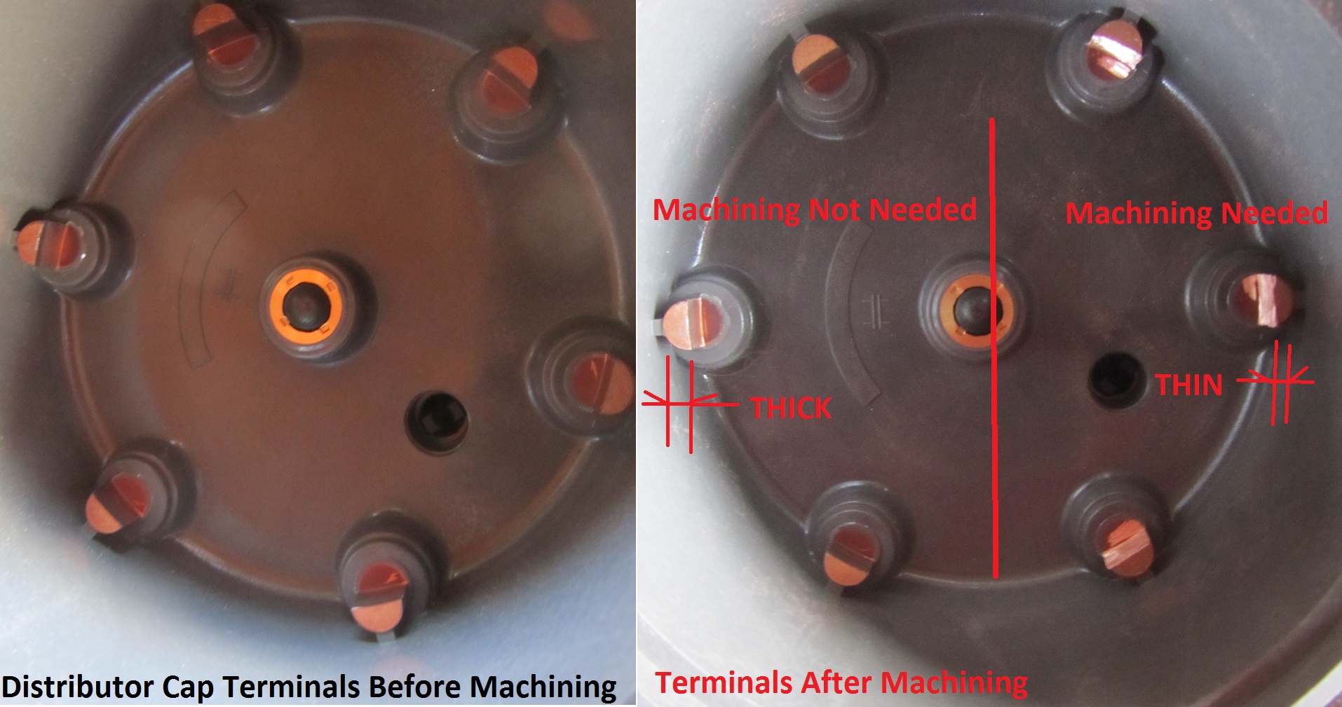
Current date Distributor Cap Terminals are machined at the factory off center. The end result is that half of the cap terminal to rotor gaps are too big and half are too small.
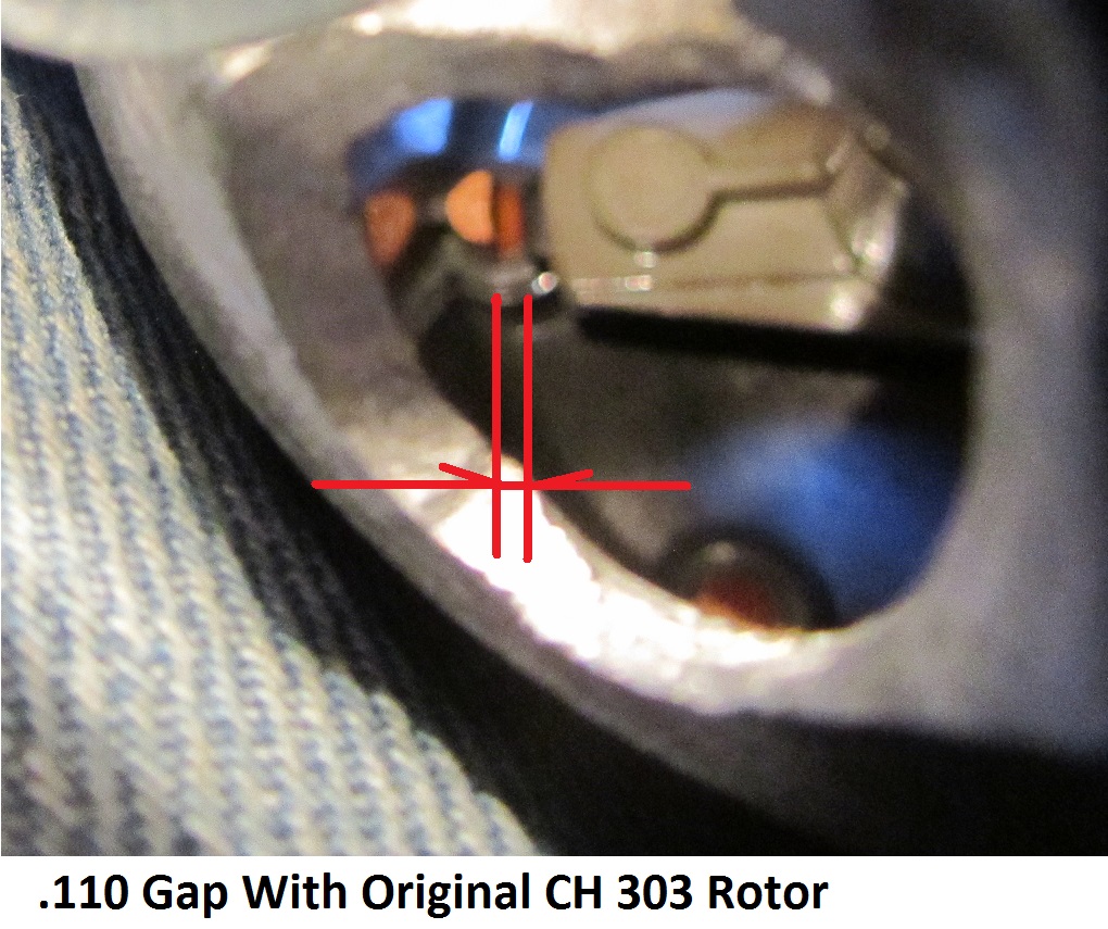
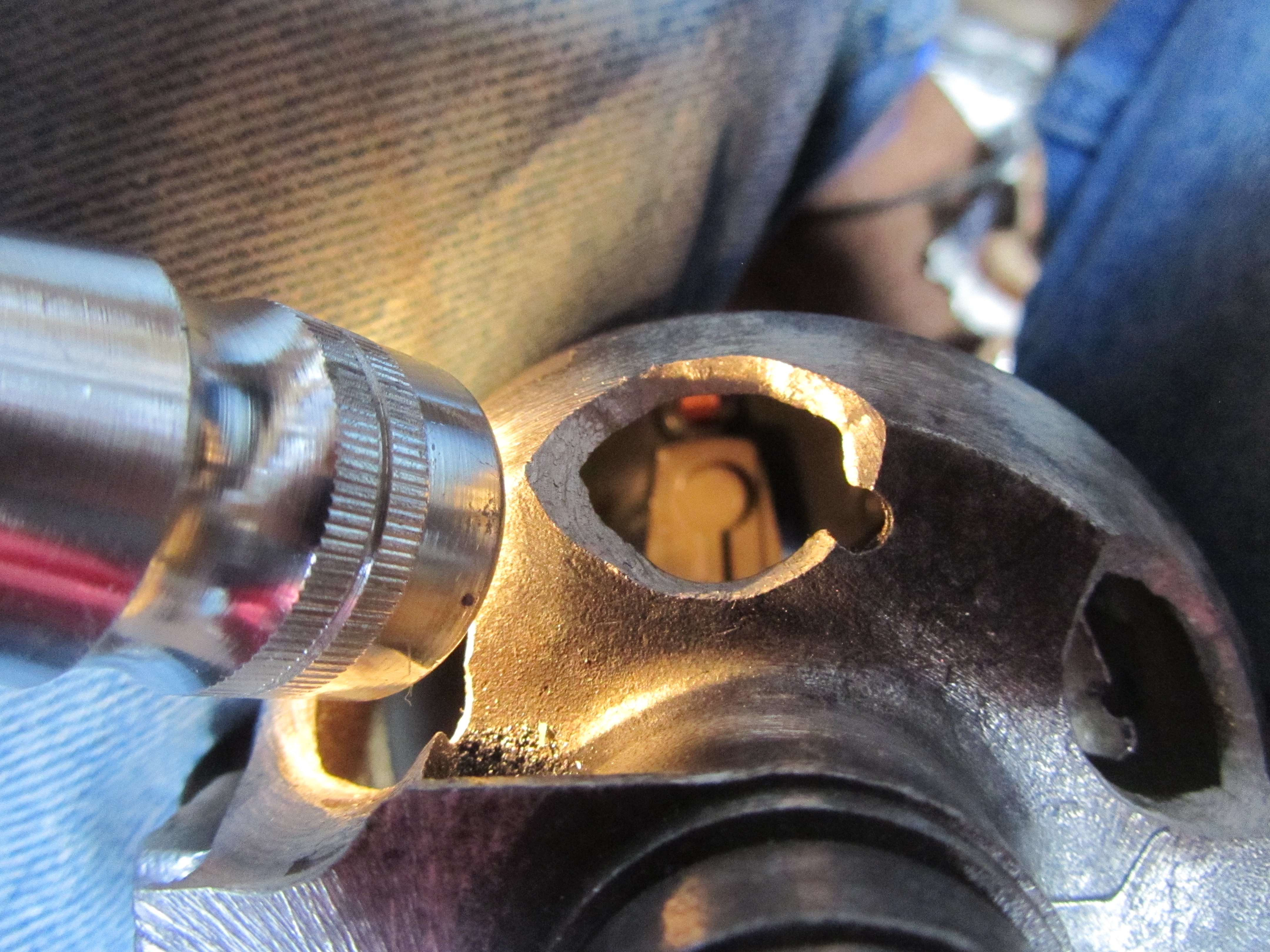
Measuring an excess gap:
Problems:
Gap between rotor & terminal use to be (more than 5 decades ago) .020-.030″ and the desired result was that coil wire voltages were near 5000 volts.
Changing the gap creates problems:
Problem 1 is that excess gaps cause a higher resistance in the secondary circuit causing coil voltage to be higher in order to fire at the plug; the sparks created in the cap are larger than at the spark plug.
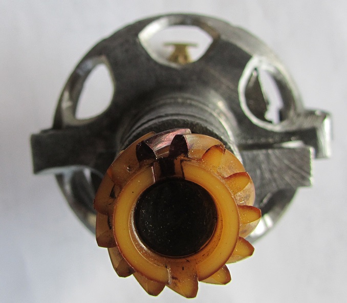
Problem 2 is that reduced gaps can result in the rotor physically dragging on the distributor terminal; plastic distributor gear and the bottom of the rotor shaft can get stripped & the rotor stop spinning.
Results:
Reduced lifespan of ignition components or engine failure to run.
Fixes:
A) Finding good caps made years ago, verifying using a gap tester, & matching rotors to caps
B) Re-machining the cap terminals, extending the rotor, & testing the final gap
Some caps are so bad they can’t be machined since the terminal post diameter is too small:
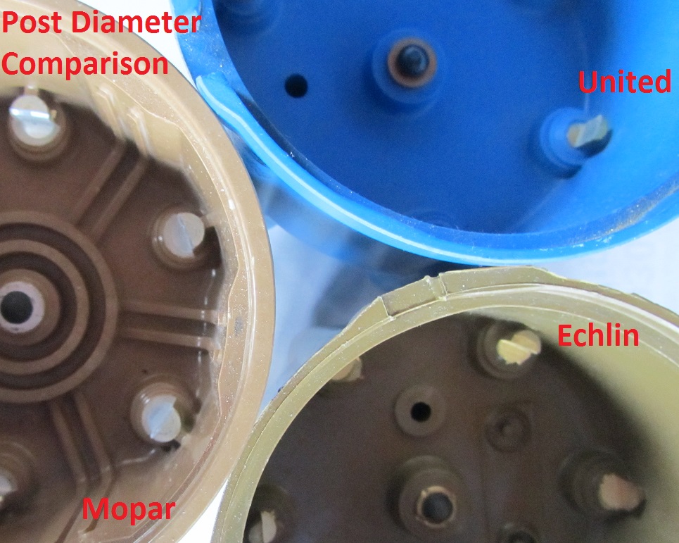
Do not buy them under any circumstance.
Finding well machined caps means going back to a cap made before the 70’s. Once the 70’s rolled around, the first problem with caps arose when gaps were opened up to allow for sloppy machining at that point in time. It’s gotten even worse since then.
Re-machining the cap terminals also means having a longer rotor to compensate for the cap terminal machining performed.
Verifying Fix:
Measuring Gaps & Coil Wire Voltage is final step in knowing that your work was successful & expectations of secondary ignition reliability will likely be met.
Tool Needed:
Whether buying the better cap or machining you’ll need a tool to verify the gaps:
The tester is made using a spare distributor, installing new rotor shaft bushings, and cutting out the peep holes needed to measure the gaps. Add a long feeler gauge & pin point lighting to be able to view the cap & rotor:
If the gaps are too large then first change the rotor to an extended one that can be purchased such as the NAPA MO3000 for slant sixes for example.
I’ll add more photos and info if there is an interest.
Measuring Coil Line Voltage To Verify Before & After Fix Results
When gaps increase at the spark plug or distributor cap the increase on coil line voltage can be used to determine the extent of the impact. A scope such as on the Sun Tester 1215 will visually display the entire cycle & peak voltage reached:
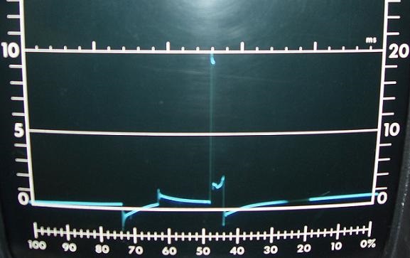
CoilWireVoltage
The above coil wire voltage shows the entire duration of the spark as well as the values at different points of the cycle. In this case 10000 peak volts indicates there is a somewhat high resistance in the secondary ignition system raising the voltage from a typical value of 5000 volts. Larger Gaps can raise resistance.
Also a tester that measures the collapsing magnetic field around the coil wire (inductance tester) can be used to capture the peak voltage in the coil wire with minor effects on the running of the engine during the process.